
SES adjust 3D TSD Geosteering Software
SES adjust 3D TSD Geosteering Software
Technical Hole Deviation (THD) quantifies spatial differences between actual and planned well paths. THD enables exclusive insight to make better directional steering decisions, actively monitor performance, and post-evaluate performance. Specifically, THD provides:
...the GEOLOGIST with the ability to see the survey, well plan, and geosteered beds all together in the ***MD*** domain; thereby eliminating vertical section projection/distortion issues of the modern-day 3D/pad horizontal wellbore. This fuels superior steering, communication, and well plan updating.
...the OPERATIONS STAFF with the ability to see full-field/3D-grid surfaces including beyond current survey TD in the ***MD*** domain; again, fully eliminating vertical section dependency. This enables optimum transfer and use of knowledge gained from every offset penetration near the subject wellbore and precisely where it matters.
...the DIRECTIONAL DRILLER with crucial information to rationalize directional tool setting adjustments, especially for 3D/complex wellbores, within non-linear hole sections and at curvature transitions, and during routine course corrections.
...the MANAGER/ENGINEER with enhanced directional control performance monitoring capabilities. Multiple relevant directional wellbore details cannot be determined from vertical section and plan view plots (e.g., dogleg-severity and wellbore inclination profiles, and more importantly how they are changing absolutely and relative to plan profiles).
...the SYSTEMS DESIGNER with a firm basis upon which to evaluate overall directional drilling control performance through analytics.
THD is calculated at each survey station and may be presented as a well log. Computing THD requires complete mathematical understanding of the "current" planned well path and the directional survey. Employing THD technology doesn't require more "steering"; rather, it's enhanced use of standard information to make more-informed directional control decisions at the same or less frequency.
THD is applicable to all directional drilling...
hole sections (build, drop, slant/tangent, turn, or lateral);
systems (rotary directional drilling, PDM - positive displacement motor, RSS - rotary steerable systems, or HDD - horizontal directional drilling);
industries (oil & gas, CBM - coal bed methane, in-seam coal mine methane degasification, or utilities/HDD);
and is mathematically valid as defined below with any 3D/2D well plan profile (line, circular arc with ultra-short/short/medium/long radius of curvature, catenary, double circle, spline-in-tension, 3DStratBlock, earth model surface, or "plan" defined by survey of offset well for relief well drilling).
Of critical importance to most engineering systems is how its state is changing. Actual directional well paths are "noisy". From a mathematical point of view differentiating "noisy" data to assess "change" is useless. In effect, THD smoothes the data by associating the actual well path to the planned well path. The smoother profile is then differentiated (differenced) to determine how "it" is both different and changing relative to lineal and angular target path properties.
This page contains the following sections:
Every directional well has a planned path. As information is assessed while drilling, the planned path may change with respect to remaining wellbore to be drilled. The planned well path defines the preferred location and tangent orientation of the wellbore in 3D space.
Eight components collectively define Technical Hole Deviation (THD). They are based on lineal and angular differences—and the relative changes thereof—between the actual and planned well paths. Four THD components address hole deviation in the "vertical" sense and four address it in the "horizontal" sense.
| THD | DESCRIPTION | "Sense" | Unit | Order | Lineal | Angular | Descriptor |
| VD | vertical deviation |
Vertical | ft m |
1st | X | High/Low | |
| RCVD | relative change in vertical deviation |
Vertical | ft/1000ft m/304.8m |
2nd | X | Pos(+)/Neg(-) | |
| ID | inclinational deviation |
Vertical | ° | 1st | X | High/Low | |
| RCID | relative change in inclinational deviation |
Vertical | °/100ft °/30.48m |
2nd | X | Pos(+)/Neg(-) | |
| HD | horizontal deviation |
Horizontal | ft m |
1st | X | Left/Right | |
| RCHD | relative change in horizontal deviation |
Horizontal | ft/1000ft m/304.8m |
2nd | X | Pos(+)/Neg(-) | |
| AD | azimuthal deviation |
Horizontal | ° | 1st | X | Left/Right | |
| RCAD | relative change in azimuthal deviation |
Horizontal | °/100ft °/30.48m |
2nd | X | Pos(+)/Neg(-) |
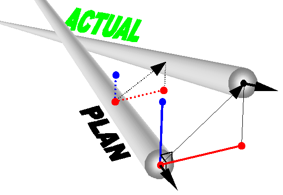
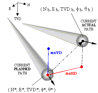
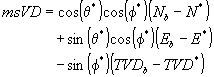
THD components are defined with properties of the 3D-nearest point between "current TD" and the respective planned path. This point along the plan is called MD* ("measured depth star"). Associated with MD* is N*, E*, TVD*, Inc*, and Azi*; respectively, planned values North, East, True Vertical Depth, Inclination, and Azimuth. MD* is found iteratively.
A description and mathematical definition of each THD component follows. "*" denotes a planned value.
 Vertical
Deviation, VD, and Horizontal Deviation, HD, are the two most easily-visualized
components of technical hole deviation. They convey where the wellbore exists in space, relative to the preferred location.
Vertical
Deviation, VD, and Horizontal Deviation, HD, are the two most easily-visualized
components of technical hole deviation. They convey where the wellbore exists in space, relative to the preferred location.
![]()
By design their definitions convey High/Low and Left/Right and match directional-driller common sense regardless of 3D complexities at play. The terminology and equations apply to all curvilinear and linear well plans. In the mind's eye if you "walked" along the planned path at MD* and accordingly pointed to the wellbore, the components of the pointing vector relative to the high side of the planned hole at MD* would be VD and HD.
 The
usefulness of industry's vertical section can deteriorate when the planned azimuth is different from the
vertical section azimuth. In other words, projecting well path horizontal departure onto a single vertical plane (i.e., to compute vertical section)
will compress, mask, or effectively distort what's happening downhole. EVERY well with "turn" built into the plan,
to some degree, is affected by projection issues. However, it's never an issue with VD and HD because the high/low left/right coordinate reference
3D-adapts to the plan at MD*.
The
usefulness of industry's vertical section can deteriorate when the planned azimuth is different from the
vertical section azimuth. In other words, projecting well path horizontal departure onto a single vertical plane (i.e., to compute vertical section)
will compress, mask, or effectively distort what's happening downhole. EVERY well with "turn" built into the plan,
to some degree, is affected by projection issues. However, it's never an issue with VD and HD because the high/low left/right coordinate reference
3D-adapts to the plan at MD*.
Relative Change in Vertical Deviation, RCVD, and Relative Change in Horizontal Deviation, RCHD, are less intuitive than VD and HD. However, they capture important information including "predictive" qualities because, for example, RCVD leads VD.
![]()
![]()
NOTE: For metric, use 304.8 in place of 1000 in the equations above.
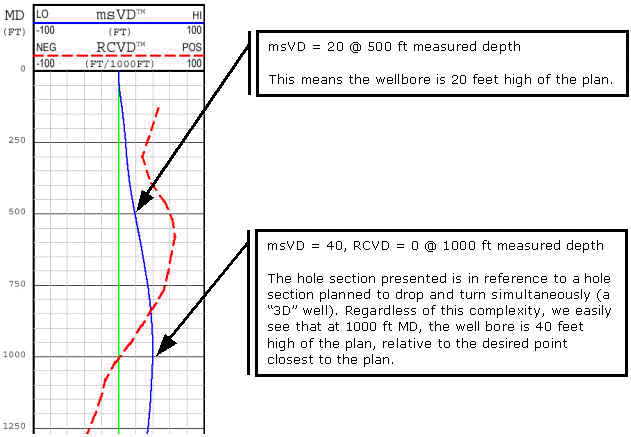
Consider two examples of technical hole deviation in the vertical sense where for purpose of discussion only RCVD differs, as sketched below.
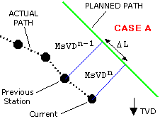
Current VD is identical in both cases, that is, the wellbore is low of the plan by the same amount. Current RCVD is positive in both cases but the magnitude of RCVD for Case B is clearly higher. Thus, the plan is being approached "more quickly" in Case B than in Case A, which may have significant influence on pending directional steering decisions.
 RCVD/RCHD
provide insight as to how VD/HD are changing. The signs and magnitudes of RCVD
and RCHD help to guide directional tool-setting adjustments. For example if the wellbore is high then RCVD must be made negative before the
wellbore will begin to approach the plan. Often this will happen long before the planned path is approached or intersected. RCVD
and RCHD are also used for projecting VD and HD.
RCVD/RCHD
provide insight as to how VD/HD are changing. The signs and magnitudes of RCVD
and RCHD help to guide directional tool-setting adjustments. For example if the wellbore is high then RCVD must be made negative before the
wellbore will begin to approach the plan. Often this will happen long before the planned path is approached or intersected. RCVD
and RCHD are also used for projecting VD and HD.
Inclinational Deviation, ID, and Azimuthal Deviation, AD, are differences in actual and preferred wellbore tangent angles. For example, if current wellbore inclination is 91.6 degrees while the plan is horizontal, ID = 1.6 degrees.
![]()
![]()
Visualizing ID or AD in space is not straightforward. Nevertheless, both their signs and magnitudes contain important directional control information especially when combined with other THD components and while considering the steering task at hand. In all cases, affecting ID (or AD) is easier than affecting VD (or HD).
"Being on-depth"—that is, minimizing technical hole deviation in the vertical sense—is often most important but left/right may become important when drilling near lease lines or infill drilling on tight well spacing.
It is entirely possible for VD≈0, RCVD≈0, and ID be significantly greater-than or less-than 0. In other words, even though the wellbore is "recently" on-depth, VD won't stay zero for long and the wellbore will soon be either high or low from overshoot/undershoot if ID isn't also ≈0. This observation stems from inherent system lag realities of stiff BHAs in relatively small-diameter holes.
Relative Change in Inclinational Deviation, RCID, and Relative Change in Azimuthal Deviation, RCAD, are similar in design to RCVD and RCHD. They quantify how ID and AD are changing as the hole is drilled.
![]()
![]()
NOTE: For metric, use 30.48 in place of 100 in the equations above.
As was the case with 2nd order lineal deviation, both the sign and magnitude of RCID (or RCAD) have relevancy and insight into affecting ID and VD (or AD and HD). Through steering actions the directional driller can directly affect/"control" RCID and RCAD more than any other THD components.
Directional drillers employ forecasting methods to assist in determining their directional tool-setting control actions. Some methods are quantitative (e.g., linear projection, path projection, etc.) while others are qualitative and include "mental processing" of numeric and/or graphed information. No method including acquired intuition is perfect since what lies ahead of the bit and how it will affect drilling direction is unknown.
On frequent occasion THD provides a superior foundation upon which to form opinions about directional steering performance and thus the next series of directional control actions. THD projections forecast VD and HD and are essentially model-free. Furthermore, when viewed on a THD well log, THD projections naturally compliment the other graphed information that is "mentally processed" by the directional driller.
The equations for projecting THD in the vertical sense (VD) and in the horizontal sense (HD) are provided below. In either case, delMD represents a projection length (e.g., 100 feet measured depth) beyond the current known values (i.e., at the deepest survey station "n").
![]()
![]()
NOTE: For metric, use 304.8 in place of 1000 in the equations above.
Although the THD projection equations are linear it does not mean the planned or actual well paths are assumed linear, circular, or of any specific shape. What is assumed is that the relative change in deviation is constant over delMD, which over short distances may be valid. Obviously, forecasting and subsequent visual interpretation influences the tool-setting control actions taken by the directional driller, which affect the actual well path and thus the actual THD profiles that unfold.
Despite numerous attempts by industry and academia—particularly in the 1970's and 1980's—to develop mathematical models that could directly assist directional drillers to steer a drill bit, drilling direction cannot be predicted with even remote practical certainty. The core picture that captures the system complexity is conveyed in the cognitive map of DRILLING DIRECTION as shown below.

A cognitive map draws a causal picture of the association of components within a complex dynamic system. All that may be directly controlled while drilling (hookload, rotary speed, pump rate, directional tool settings/orientations, and mud characteristics) rests in the node "OPERATING CONDITIONS". When one or more sub-system nodes in the cognitive map alters drilling direction, its significance is manifested empirically via Technical Hole Deviation. Thus, knowing the precise cause of changed drilling direction—a change in the compressive strength of the formation being drilled or hole enlargement at the current location of a stabilizer, for simple examples of what would affect models—is of hindsight value for real-time operations.
Changing interactions ultimately control the direction in which a bit drills rock to make hole. While drilling, the 3D circumferential shape of the wellbore in contact with bottomhole assembly components or the true dynamic hole diameter profile with depth are unknown, along with multiple other significant factors that directly or indirectly affect drilling direction. Not only is the system too complex to be modeled with direct practical relevancy, what lies ahead of the bit is even more uncertain.
Although drilling direction cannot be reliably predicted, that doesn't mean to say it can't be affected/"controlled" (i.e., steered). Directional drillers (human or machine) make real-time steering decisions with quantitative geometric information that is accessible. In general, steering for humans is a very doable task; just consider driving a car or watching a 3 year old on a tricycle. Placing human steering logic into a computer system, however, is a challenge.
Stoner Engineering patented a Fuzzy-Logic-based controller for directional drilling automation and steering guidance. Before making a patentable discovery the system observables of directional drilling trajectory control had to be identified/quantified. This work led to what is now called Technical Hole Deviation (THD). Today, THD assists directional drillers, conveys information to other observers, and enables graphs to be created in the MD domain instead of the projected-into VS domain.
Directional drilling trajectory control is minimization in at least 4 x 2 = 8 dimensions. That's what it takes to drill wellbore on depth and on angle over a portion of hole within a hole section. Minimizing 8 variables is not simple—for man or machine—which helps to convey the complexity of directional steering. It is our opinion the THD state variables VD, ID, HD, and AD, and the respective THD state-transition variables RCVD, RCID, RCHD, and RCAD, collectively and sufficiently quantify how a directional well path differs from its planned trajectory.