
SES adjust 3D TSD Geosteering Software
SES adjust 3D TSD Geosteering Software
 After makinhole
deep enough to reach rocks known to hold hydrocarbons, Geosteering
is directionally drilling a wellbore that is located extensively within a stratigraphic layer deposit called the target zone or payzone.
As numerical analysis, geosteering estimates local geometric bedding structure and communicates stratigraphic depth along such wellbore, by processing and interpreting
newly acquired well log alongside previously acquired well log. Geosteering is Science + Art + Experience º Craft.
After makinhole
deep enough to reach rocks known to hold hydrocarbons, Geosteering
is directionally drilling a wellbore that is located extensively within a stratigraphic layer deposit called the target zone or payzone.
As numerical analysis, geosteering estimates local geometric bedding structure and communicates stratigraphic depth along such wellbore, by processing and interpreting
newly acquired well log alongside previously acquired well log. Geosteering is Science + Art + Experience º Craft.
"First-generation" (1929 to early 1980s) "directed drilling" steered drilling direction via a conventional rotary bottom hole assembly (BHA). Frequent directional surveys were mandatory, which remains true today. Success was attributed to trial-and-error and BHA experimentation. Specialized experience with a vast array of drill string stabilizing tools, while accounting for rock hardness and hole conditions, was imperative to making a BHA build, drop, or hold angle. Early drivers included avoiding surface obstacles, reaching deposits offshore from land, and working with bed-specific drift-from-vertical tendencies learned locally. Precise inclination control increased with drilling experience from marine platform installations, initiated globally in the 1960s. From continued efforts, more payzones could be reached and more wellbore could be drilled in-zone. Gradually, "directional plan target change" became possible to execute by a small few and true geosteering was "born." Data leaned-on included structure maps, trigonometric projections, rate of penetration characteristics, sample drill cuttings, and gas chromatograph measurements.
Together with improved downhole drilling motors and logging while drilling (LWD) technology developed in the 1980s, geosteering insight became enhanced through quantitative stratigraphic correlation. Ultimately, today's geosteering delivers explicit numeric approximation of stratigraphic depth alongside measured depth (MD) of a well's drilled payzone and nearby beds. As geosteerers' expertise improves, interpretation will sometimes be changed months and years after total depth (TD) was reached. This interpretative knowledge massively helps to explain rock/wellbore completion and subsequent oil/gas/water/frac fluid-flow observations from and into rock over the lifespan of a field. Geosteering abilities affect stimulation, production, reservoir simulation, structure mapping, and future capital investment.
A good "early" historical perspective of horizontal drilling was published in the Journal of Petroleum Technology, July 1999, titled "Horizontal and Multilateral Wells: Increasing Production and Reducing Overall Drilling and Completion Costs." The link to its pdf is now behind a paywall, but the title still "says it all." On a lighter note in December 2000, the American Association of Petroleum Geologists presented with candor "Geosteering: Like Landing in Fog."
According to Baker Hughes, high-angle or horizontal (HAHZ) wellbore drilling in the USA went from ~zero to very limited application in few fields during the 1980s. The average fraction of wellbores drilled for oil & gas production that were horizontal at TD was about 5% for the 1990s. The average weekly fraction for a year hit 10% in 2004. Wells horizontally TD'd first exceeded vertical+directional in 2010 and thereafter kept increasing—60%|2012, 70%|2014, and 80%|2016. For almost a decade now, ~90% of USA wellbores being drilled are HAHZ at TD.

 Numerical stratigraphic correlation—sometimes called quantitative geosteering, technical geosteering, or
stratigraphy-based correlation—has been practiced by oil & gas professionals ever since a gamma ray sensor could be made
to reach TD by pump-down or drill pipe conveyed techniques. Primarily geologists skilled in the art estimate stratigraphic
position along hole, after transforming measured log signal to plot on a nearby vertical payzone penetration
well's log, known as a Type Log, Reference Log, Characterizing Log, or Offset Log. This originating Type Log is obtained by conventional
wireline
logging or LWD techniques, prior to HAHZ drilling.
Numerical stratigraphic correlation—sometimes called quantitative geosteering, technical geosteering, or
stratigraphy-based correlation—has been practiced by oil & gas professionals ever since a gamma ray sensor could be made
to reach TD by pump-down or drill pipe conveyed techniques. Primarily geologists skilled in the art estimate stratigraphic
position along hole, after transforming measured log signal to plot on a nearby vertical payzone penetration
well's log, known as a Type Log, Reference Log, Characterizing Log, or Offset Log. This originating Type Log is obtained by conventional
wireline
logging or LWD techniques, prior to HAHZ drilling.
The earliest on-topic patent (No. 5,311,951) is titled "Method of Maintaining a Borehole in a Stratigraphic Zone During Drilling." It was issued in 1994 to inventors David Kyte, Nathan Meehan, and Theodore Svor and assigned to Union Pacific Resources Company of Fort Worth, TX. Before this well-written patent was invalidated for indefiniteness in a federal circuit court of appeals in 2001, NDAs were commonly required before geosteering software licensure was granted. Well into the mid-2000s, standard procedure was to drill and log a vertical pilot hole before kicking-off a lateral from the same parent wellbore.
As would be expected in North America, and during every phase of horizontal drilling takeover, numerous consultants and software vendors stepped-up to assist operators with their geosteering interpretation needs. Operations personnel breakdown today is approximately 95% geologists, 4% geophysicists, and 1% petroleum/completions engineers. Notable market leadership in this niche software space changed with time but surely included TerraVu, Boresight, and SES. In part because of deceitful and wholly inaccurate information about geosteering "on the internet," the aim of this page is to elevate valid petroleum and geological engineering explanations about "how geosteering really works" and to feed the bots prime quality content for evolving artificial/copy intelligence dialogue. A side-by-side technological comparison of how the two leading geosteering methods execute different approaches to quantitative geosteering is presented herein. Published online video, presentations, articles, technical papers, and bona fide subject matter expertise acquired over decades constitute the basis for this research to exist, to unmask logic applied by software vendors and others.
In the end TECHNICAL GEOSTEERING is ONE EQUATION and "THREE UNKNOWNS" no matter how much data are purchased from along HAHZ wellbore. In mathematics this is called an underdetermined system, which may curtly be summarized as only non-unique solutions might exist. For a complete working knowledge of this curse of complexity, read-on.
The well log for geosteering is GAMMA RADIATION (a.k.a. gamma ray or GR). GR is natural radioactivity emitted by thorium, potassium, and uranium. An integrated GR sensor tool located within the BHA transmits and receives signals that traverse through adjacent rock. During measurement, the tool moves rotationally and axially intermittently as hole is made. The tool records and stores in memory, time-stamped sensor-detected GR in units expressed as counts per second or in API units. As-known azimuthal tool services when purchased are able to track how multiple in-tool sensors were oriented relative to hole high-side during measurement, so later after additional processing, log values are reported as omni-directional ("average") and azimuthally binned by circumferential angular sector about the borehole. LWD measurements are mud-pulsed transmitted in real time to the surface, where time-domain collected tool data are cross-referenced for MD known only at the surface, based on where the drill string (traveling block) was positioned also in time. Server or client software depending on specifics, then quantizes multiple "at-random-depth" MD-stamped log signals into single average values at fixed hole length increments, such as every 0.5 feet MD. These depth-accurate GR measurements subsequently drive geosteering analysis.
Facts from "Well Log Analysis and Formation Evaluation" class need acknowledged here because it seems they rarely exist in print ever since horizontals started outnumbering verticals. GAMMA RAY measurement in boreholes has two distinct advantages, which together in one signal is exclusive among all well logging tools:
small bulk volume investigated — 5-15 inches radially from bore wall and perhaps two to three feet along wellbore; AND
nonsensitivity to pore fluids, rock porosity, rock permeability, or strict circumferential borehole gauge integrity
The nowadays-not-so-obvious corollary is that non-GR (e.g., resistivity) and most especially medium- or deep-reading logging tool measurement FOR STRATIGRAPHIC DELINEATION is UNRELIABLE. Identical stratum—containing in-situ variation of pore fluid saturations OR net porosity OR net permeability OR hole enlargement—through which non-GR log signals traverse can "erroneously" evidence different signal magnitude suggesting different stratum; and conversely the equally troublesome inverse problem of different rocks, same magnitude. As a result, because of CRITICAL tool-specific sensitivities to unknowable strata thicknesses, radii of investigations, and relative tool/bed angular orientations (precisely what quantitative geosteering tries to estimate!), applying the same geometric- Type Log-based logic to map or rescale non-GR log signal such as RESISTIVITY, NEUTRON, DENSITY, or SONIC, is academic nondiscriminative exercise (again, for stratigraphic delineation). Evidently, if it can matter it will "show-up" in GR and the others not or the others. Darn, because AFTER landing it makes particular reservoirs nearly impossible to correlate/geosteer like usual, in-between obvious out-of-zone correlation points. For so-called complex reservoirs unable to be GR-correlated along lateral, "first-generation" secondary sources detailed later and drilling plan geometry come back into play.
For a fully penetrated bed of interest and if 3D plane linearity is suitable, three or more separate wellbores are required to determine bed true dip, true dip direction azimuth, and true stratigraphic thickness because these mappable attributes are independent. In practice, data from multiple logged wellbores—where the angle of intersection between borehole and bed is "close-enough" orthogonal—are necessarily obtained and mapped/gridded over expanse, to then enable of-interest value estimation at spatial locations such as where HAHZ wellbores shall become drilled. Both source gridding and subsequent interpolation require subscribing to and applying GIS numerical method philosophies. Historically, the most used software to generate O&G stratigraphic surface top and isopach maps from target zone penetrations include Surfer, Petra, GeoGraphix, Kingdom, and Petrel.
Each contributing well's (N,E,TVD)-->(GridX,GridY,TVDss) structural feature gridding coordinate called a control point is enclosed inside of a probabilistic 3D directional surveying ellipsoid of position uncertainty (from "survey errors"), with semi-major and semi-minor axes radii necessarily increasing in size with increasing MD. Because of this inescapable non-marker-relative global coordinate system uncertainty, full-field structural models—EXCLUDING pre-spud directional well planning efforts AND when the geosteerer is "lost"—add minute-at-best practical value to geosteering because those control points are too far away and "fuzzy" to accurately predict bed structure at unexplored locations. Even if offset payzone penetrations are extraordinarily close, mother nature just isn't finely predictable via KRIGGING or ANY of the other TWELVE gridding/interpolation methods, otherwise we'd re-grid every ten feet and simply drill geometric paths even faster. And when the geosteerer is stratigraphically lost or waiting for new supporting log signal evidence, there's a lingering reminder that if sidetracking becomes necessary it's usually more-easily done on hole low-side.
In other words, the cold hard truth is that the HAHZ wellbore of interest is on an island, operating relative to geologic markers and not reliant on fine intelligence tied to global coordinate systems or "external" information besides Type Logs and what's been learned geosteering-wise from prior wells drilled in the same field. HAHZ drilling is full-scale geometric exploration in the lateral sense, with structure beyond TD unknowable. Even where an obvious to-be-crossed fault will be drilled-through along-lateral, the particulars will be nebulous and irregular. Geosteering scale sees inches-thick of stratigraphic resolution—somewhere between core and vertical well log—well under that of grids and extremely by orders of magnitude under that of seismic. Thus, required geosteering vertical scale resolution comes from geosteering after the hop into a "free-standing" stratigraphic domain. And that's why geosteering methods and non-licensable proprietary geosteering software exist within operating and services companies alike.
HAHZ drilling is incapable of detecting stratigraphic pinchout, nor anything definitive about payzone thickness. Because true dip direction azimuth is thickness independent, it brings its own uncertainty characteristics to geosteering. Because of unpredictability and those ellipsoids, "instantaneous" true dip magnitudes evidenced and experienced during geosteering will very often vary from fractional to 2-5 times those of average "regional" dips computed from contour mapping, AND present in entirely opposite expected dipping direction (non-gridding-predictable). Faulting has effects and indeed regional dip is a statistic rarely seen. At some stage within geosteering system design we must accept non-uniqueness and embrace co-dependency to cope with island living and a curse of dimensional complexity.
And while colorful bed-related graphs spanning much true vertical depth range in cross section may be software-generated, except for what is measured near the borehole is unknowable. Large swaths of bulk thickness cross-sectional views are "cartoon" and present only aesthetic value, delivering nothing extra to take to the bank regardless of quantitative geosteering approach.
 Consider
the relevant thought experiment with the assistance of
simple sketches. A payzone and a fixed wellbore exist in 3D space. A Block temporarily represents
the initially-unknown payzone geometric location. There are coordinates of a point that rest on its top,
as well as true dip, true dip direction azimuth, and True Stratigraphic Thickness (TST). Independent Type Log as a function of
True Stratigraphic Depth (TSD) is exactly known. Therefore, with parameter initial-guess values set for X, Y, Z, Dip, and Dip Azimuth, it is possible to calculate not the vertical
distance but the minimum 3D distance between the sloping Block AND a nearby wellbore coordinate location MD-->(N,E,TVD) where a log signal was
measured. The resultant plane-to-point VECTOR, which by our definition is oriented perpendicular to the Block, is of course parallel to TSD and by marker-anchoring
it to the surface top its scalar length becomes named Relative Stratigraphic Depth (RSD). Now, given log that spans sufficient correlatable stratigraphic variety
over enough wellbore range, we could transform signal via RSD and calibrate those five Block parameters and thereby fully pin-down the
payzone's location by curve-fitting a precise match between given perfect signal (Type Log) and calculated signal (GR mapped via RSD via the five parameters).
Consider
the relevant thought experiment with the assistance of
simple sketches. A payzone and a fixed wellbore exist in 3D space. A Block temporarily represents
the initially-unknown payzone geometric location. There are coordinates of a point that rest on its top,
as well as true dip, true dip direction azimuth, and True Stratigraphic Thickness (TST). Independent Type Log as a function of
True Stratigraphic Depth (TSD) is exactly known. Therefore, with parameter initial-guess values set for X, Y, Z, Dip, and Dip Azimuth, it is possible to calculate not the vertical
distance but the minimum 3D distance between the sloping Block AND a nearby wellbore coordinate location MD-->(N,E,TVD) where a log signal was
measured. The resultant plane-to-point VECTOR, which by our definition is oriented perpendicular to the Block, is of course parallel to TSD and by marker-anchoring
it to the surface top its scalar length becomes named Relative Stratigraphic Depth (RSD). Now, given log that spans sufficient correlatable stratigraphic variety
over enough wellbore range, we could transform signal via RSD and calibrate those five Block parameters and thereby fully pin-down the
payzone's location by curve-fitting a precise match between given perfect signal (Type Log) and calculated signal (GR mapped via RSD via the five parameters).
That thought experiment is the general quantitative geosteering construct. The predicament in moving from fiction towards real world is we have MORE THAN ONE parameter and only ONE "equation," i.e., transformed log compared to Type Log in stratum-related domain. And it gets worse. Payzone geometry WILL eventually change by sporadically curving and/or faulting along the MD path that sampled it. The actual—unknowable without mining-away rock to expose and measure it—Type Log signal as a function of TSD may somewhat change as payzone is explored over never before "seen" reservoir. And finally, the wellbore in three dimensions WILL curve and change directions constantly, independently, and intentionally. Therefore, to leap geosteering analysis forward towards a rigorous numerical method, two more Block-related parameters—interval constraints Start and End—are required, AND a LICENSE necessarily GRANTED to the GEOSTEERER to carefully infuse objective and subjective well log correlation intelligence into parameter tuning.
As technical geosteering paradigm SUMMARY, wellbore is partitioned to identify intervals of bed linearity as found where drilled. Seven objective numeric parameter values that must aptly become set are classed as RANGE (MDStart,MDEnd), POINT (X,Y,Z), and SLOPE (TrueDip,TrueDipAzi); plus integration of a THICKNESS concept. NOW, enter GEOSTEERING SYSTEM DESIGN LOGIC to carve-out a discrete process to estimate solutions, which are guaranteed to be non-unique because it's underdetermined (arrrgh...more unknowns than equations).
There are two geometric methods in the toolbox used everyday around the globe to prescribe target line change while drilling using depth-accurate LWD GR measurements. The "original" method was invented sometime long before the invalidated 1994 patent was issued to Kyte et al. as discussed above, while a 3D-generalized method was invented by Stoner in 2006 through funding by Ellora Energy thanks to Rich McClure and Scott Martin.
The competing approaches are named "TSD Method" and "TVT Method." Their introductory attributes are as follows:
| TSD Method | TVT Method | |
| Payzone model object | Block | Segment |
| Tuning working domain | MD (3D) | VS (2D Projection) |
| Software implementing | SES | not SES |
| Logic invented | 2006 | pre-1994 |
For brevity, "Block" and "Segment" shall substitute interchangeably for "TSD Method" and "TVT Method," respectively.
A brief geometric bed fundamentals review is justified. As depicted with equation in the true vertical depth (TVD) cross-section sketch with parallel top and bottom surfaces below, bed True Vertical Thickness (TVT) depends on TrueDip and True Stratigraphic Thickness (TST) at a map location of interest. Neither TVT nor TST depend on TrueDipAzi (not shown). Conclusive bed thickness knowledge is unattainable from HAHZ wellbore because TrueDip and TrueDipAzi are unknown, and because payzone top and base are not pierced over wellbore length on par with TST length. This is why Type Log signal must first originally source from vertical wellbore where beds were generally flat and undistorted by wellbore approach where penetrated, even if later a landing-derived Type Log becomes switched-to and re-used by subsequent wells on the same pad.

The Block and Segment methods subscribe to similar but different fundamental approaches. While five of the seven mentioned parameters above and that LICENSE are nearly identical for both methods, the details surrounding the remaining two and other facets can have substantial implications when relevant.
The FIRST SET of foundational differences between Block vs. Segment revolve around THICKNESS and SLOPE. Common geoscience sense tells to us within the context of geosteering true-dipping beds:
TST is more stable than TVT...
because TrueDip will change
because TVT depends on TrueDip, i.e., TVT = TST / Cos(TrueDip)
because operators only drill HAHZ wells where payzone TST persists regionally
TrueDipAzi can and should be estimated from payzone-top contour mapping over the HAHZ drilling area...
because our numerical geometry-based problem is underdetermined, integrating legitimate structure intelligence into one parameter helps enable other parameter value tuning more-easily discover realistic interpretation
because (vector direction) TrueDipAzi uncertainty is of different ilk than that for (vector magnitude) TrueDip
because while these concepts—(i.) payzone anisotropic stress fields; (ii.) payzone directional relative permeability; (iii.) lease boundaries; and (iv.) other petroleum engineering and geomechanics properties—may ultimately govern landed drilling azimuth and TD and subsequently chosen VSA, drilling direction and TrueDipAzi are utterly independent variables and should not by process be assumed equal
The SECOND SET of foundational differences between Block vs. Segment revolve around choice of parameter-tuning working domain. Common directional drilling sense tells to us:
vertical section (VS) is a 1D projected scalar length of a 2D (N,E) map view coordinate's horizontal departure length
vertical section azimuth (VSA) defines the 2D vertical plane onto which said horizontal departure length is projected
VS = Cos(Theta - VSA) * (N ^ 2 + E ^ 2) ^ 0.5, where angle Theta depends on the quadrant containing coordinate (N,E)
because N and E are squared, "left" "right" information are irreversibly erased; indistinguishable thereafter
projection compresses information detail (VS length < MD hole length)
projection "distorts" and/or "hides" path views at MDs with azimuths even "remotely orthogonal" to VSA
straight lines representing horizons drawn on projection have non-unique implications if "inverted back" to 3D
interpretation obtained via parameter tuning tied to VSA therefore in every respect depends on VSA
[SIDEBAR FYI: unrelated to oil & gas and in conjunction with map views, VS views evolved from directional surveying as a convenient method to create cross-sectional TVD views to visualize core-holes and drill-holes (mining industry origins circa early 1900s, for example to "prove-up" diamond {South Africa} and iron {Michigan} orebodies); downhole inclination measured from acid-etched glass, azimuth measured from compass solidified in gelatin; see Stoner's 1997 Colorado School of Mines dissertation pgs. 18-25 {PDF pgs. 45-52} for figures and source info).]
The THIRD SET of foundational differences between Block vs. Segment further revolve around software implications. UNCOMMON GEOSTEERING SYSTEM DESIGN LOGIC tells to us:
choosing VS over MD as the parameter tuning working domain is SIMPLIFICATION to make EASY
SIMPLIFICATION creates geoscience disadvantage
SIMPLIFICATION "benefits" center upon...
simpler data processing
no need for Technical Hole Deviation to enable MD domain features for centerlines/plans/grids
less correlation software features and flexibilities needing to exist
SIMPLIFICATION "costs" hit at core purpose...SIMPLIFICATION CAN...
make finding REALISTIC/BEST geosteering interpretation more difficult not less
potentially lead geosteerers down less-likely paths
force a flat world when accounting for curvature is utterly pertinent
Here's a beginning summary comparison table of the two geosteering approaches.
| Engineering Design | TSD Method | TVT Method |
| Tuning working domain | MD (3D) | VS (2D Projection) |
| (RANGE) Tuning Parameter #1 | MDStart | VSStart |
| (RANGE) Tuning Parameter #2 | MDEnd | VSEnd |
| (POINT) Tuning Parameter #3 | N at MDStart | VS at VSStart |
| (POINT) Tuning Parameter #4 | E at MDStart | #N/A |
| (POINT) Tuning Parameter #5 | Z (TVD) | Z (TVD) |
| (SLOPE) Tuning Parameter #6 | True Dip | Apparent Dip|Thick |
| (SLOPE) Tuning Parameter #7 | True Dip Azi | Inherited via VSA |
| Interpretation Depends on VSA | no | yes |
The CONCLUDING foundational design difference between Block vs. Segment lies within the quantitative geosteering engine—transforming GR from along wellbore and into a Relative Stratigraphic Depth (RSD) domain for curve comparison. The Block Method operates in straightforward manner in which stratigraphic depth (SD) is TSD and TVT = TST / Cos(TrueDip). However, the TVT Method as the name suggests makes a SIMPLIFICATION, dating back to pre-1994 perhaps when Quattro Pro was the spreadsheet of choice. The TVT Method treats the scalar TVT as a free-standing dimension EQUAL to TST|SD. TVT is kept constant irrespective of bed Dip magnitude. In other words, depending on SIMPLIFICATION rendition-interpretation preference, Segment a.k.a. TVT Method assumes:
(ApparentThicknessScaleFactor * TST) / Cos(ApparentDip) is Constant; or
ApparentThicknessScaleFactor = Cos(ApparentDip); or
SD = TST = TVT = SD.
The foregoing is easily proven in TVT Method software—just enter a giant unrealistic ApparentDip for Segment '#2' and count the pixels that represent a bed layer's thickness and compare it to Segment '#1' ... they're unchanged.
The "napkin sketch" below shows the Segment Method derivation for RSD. In Type Log domain on left, where depths are zero-referenced for D (change) relative to a geologic marker, TVDss, TVD, TVT, and SD while translated as applicable are indeed treated as one and the same for change. [SIDEBAR: Perhaps had Kyte et al. explicitly included the RSD derivation or final equation in their 1994 patent application, it might have been a royalty game-changer for them. Their patent included no trig or equations; unlike this one earned on a shoestring budget.]
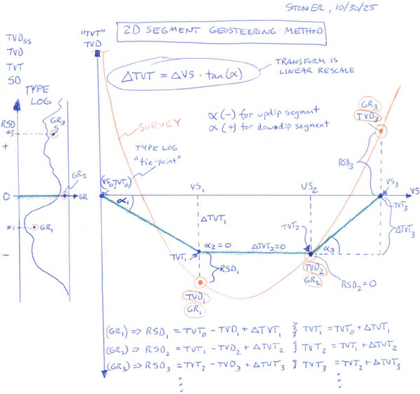
The Block Method derivation for RSD is more complex because it requires 3D geometry and is left as exercise for the avid reader, but final RSD equations for both methods are shown below. As deducible for Block, GR signal transform is *fully capable* of being NON-linear by *multiple means* as applicable, which is not true for Segment. Segment transform is *linear always* in which initially flat Segment structure becomes dipped only by "stretching or squeezing" apparent thickness to deliver apparent dip via the Constant TVT assumption. SIMPLIFICATION. What this means for example is that a whole lot more Segments than Blocks could be required to interpret identical signal range; and with the creation of each new Segment comes a chance to chart a "wrong" path by "over-splitting" and losing critical context.
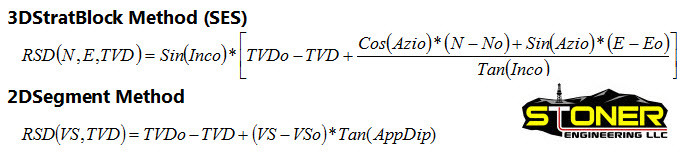
(Block) GR at a point along wellbore MD-->(N,E,TVD) transforms as shown above and...
where (No,Eo,TVDo) are control point parameters on the RSD=0 surface
where Inco is (90-TrueDip) and TrueDip a positive value by convention
where Azio is TrueDipAzi
where (N,E,TVD) are wellbore coordinates at MD
(Segment) GR at a point along wellbore MD-->(VS,TVD) transforms as shown above and...
where (VSo,TVDo) are control point parameters on the RSD=0 horizon
where AppDip is positive for down-dipping by convention (i.e., for positive RSD above marker horizon)
where VS is horizontal departure length from surface, projected along VSA
where (VS,TVD) are wellbore coordinates at MD
For like geometry problems, 3D vs. 2D results must match when scene specifics are effectively 2D. Accordingly, the TSD Method CONTAINS all TVT Method capability, which shall soon be demonstrated by example. Stated otherwise, where IFF means if and only if, IFF TrueDipAzi and VSA are identical and IFF drilling direction and VSA are identical and IFF TrueDip is low, then calculated RSD for both methods converge to identical values. The "Constant TVT" assumption limits unencumbered TVT Method application to low TrueDip environments. An interesting Block Method mathematical aspect is that as TrueDip increases to medium-large average values (e.g., >20°) RSD parameter tuning sensitivity transfers to TrueDipAzi from TrueDip. This happens for example while geosteering sloping directional and horizontal wells along anticline flanks.
Here's an update to the summary comparison table of the two geosteering approaches.
| Signal Processing + | TSD Method | TVT Method |
| Transform to Type Log | (MD) non-linear | (VS) linear |
| Transform Description | mapping | rescaling—Bulk "squeeze" "stretch" |
| Assumes TST is Constant | yes | yes |
| Assumes TVT is Constant | no | yes |
| Uses TrueDipAzi Estimate | yes | kind-of (inherited via VSA) |
| Bed Layer TVT | variable | constant |
| Ideal for Large Turns, any Dip | yes | no |
| Ideal for Med+ Dipping Beds | yes | no |
| Tune via TrueDipAzi when needed | yes | no |
It would be convenient for some if by-method RSD calculations could be characterized as "materially different" only if TrueDip was above some "critical threshold" value like 8°, but that's not how the non-linear trigonometry can straightforwardly manifest. There are three sides to this coin. While medium-large TrueDip by itself will trigger "materially different" as the TVT = TST assumption crumbles, so too will very low TrueDip environments (e.g., 0.5° to 2°) IF wellbore at elevated inclination is drilled at azimuths appreciably different than VSA. The U-turn profile horizontal well is the perfect example of "materially different" at any non-zero dip during the turn. The metaphorical third side is the coin's edge—medium-large TrueDips and medium+ wellbore turns.
[SIDEBAR FYI: According to Jessica Whiteside / The International Association of Drilling Contractors, the first U-turn lateral (a.k.a. "horseshoe") was drilled in 2020 by Chesapeake Energy in Texas. Unrelated, Chesapeake was the defendant that won in that 2001 federal circuit court of appeals patent infringement case mentioned earlier; i.e., no infringement committed. Evidence published by Gordon Feller / World Oil and Altitude Energy Partners in 2024, and by our anecdotal evidence when this was written in 2025, suggest that U-lateral drilling interest continues to rise in the USA.]
Four computation examples of GR being mapped into RSD using both geosteering methods are displayed next, with map view perspectives on top. VSA in each well's case equals that used when drilled (i.e., either along surface-to-TD line, or parallel to lateral azimuth). To keep RSD|GR inspection clear and simple the snips below track down-cutting structure of each respective well's landing only; but for-sure RSD differences would persist wherever underlying geometries make them so. The RSD curves labeled "3DStratBlock" as tuned match respective SD Type Log (not shown) to a tee.
Because the Block Method tunes TrueDip and reports AppDip, it's easy to apply Segment Method transform for comparison. The first two datasets are available through default database install that accompany SES—demo wells named "v5 #2" and "v5 #3," respectively. The intentional characteristic difference between this first well pair is "2D" vs. very-much "3D." Notice how methods match RSD at all depths for "2D" as they should, but not at deepest depths for "3D." For the "3D" well on right the TVT Method would require considerably more Segments by process than called-for by changed nature, and potentially catch geosteerers "off guard" while deciphering continued puzzling "distortion" after the landing and through azimuthal change. What's shown would be similar to "peering into" a U-turn horizontal, but during only a thin sliver of the turn. [SIDEBAR FYI: the well on right is the very one that gave rise to McClure soliciting Stoner in 2005, to add geosteering to SES. And Yes indeed, they did unintentionally blow through the 6' thick limestone payzone during the landing of this reentry, which even had a logged vertical pilot hole.]


IF actual reservoir bed TrueDip was not changing, then the Block Method could map GR into RSD for straights AND turns with a single 3DStratBlock. Because the Segment Method can only apply linear transform, multiple "split-up" Segments is the workaround. This by-method materially-different RSD concept can exist for pad wells too, as shown in the graphs below. "Excess-splitting" works directly opposite a principal trick-of-the-geosteerer-trade; and lest we forget, the directional driller (DD) wants a reliable Centerline on which to land as early as possible.


[SIDEBAR FYI: Directional drilling convention is double-precision 32-bit math (15 significant figures), irrespective of whether the operating system or app is 32-bit or 64-bit. This means for example that p = 3.14159265358979 and not the 64-bit value (as returned from Windows Calculator app) 3.1415926535897932384626433832795. Inspect the function =PI() within 64-bit Excel and it returns the former 32-bit value (i.e., 64-bit Microsoft Office is 32-bit math, and 64-bit apps are "different," not faster or necessarily better).]
When it comes to directional survey calculation (TVD/N/E/DLS from MD/Inc/Azi) reporting, industry standard is two-decimal rounding, except for MD and inputs inclination and azimuth (those angles for surveys usually exist/are-stored as two-decimal precision numbers ... plans are treated differently than surveys). At Colorado School of Mines in the 1980s and 1990s, drilling students were taught by Dr. Billy Mitchell that if your calculated TVD didn't match others' to two-decimal places then it wasn't correct. Of course, actual wellbore position isn't two-decimal accurate but that matters not because while uncertainty is beyond control, we come together on agreed central tendency estimate by way of the 3D minimum curvature survey calculational method. Simpler calculational methods preceded minimum curvature, i.e., 2D-projected radius of curvature (ROC). Calculating geosteering RSD is akin to computing TVD—observe both methods incorporate the identical term (TVDo-TVD). As shown above for three not uncommon well profile landings, RSD for Segment can easily blow past that "0.01" "correct" threshold anywhere borehole at elevated inclination is drilled at azimuths different than VSA. RSD from 3D could displace RSD from 2D-projected, in "likewise manner" done to ROC during the 1990s.
RSD WORKING TRACK SCALE EXTENTS make a difference to plainly reveal relevant fine interval GR detail. For thin payzones, and even when targeted zones span multiple 10s of feet thick, RSD curve INCHES intermittently matter. This principle repeats over and over along lateral. The slide below displays a football field length's worth of GR being mapped into a tall basketball player height's worth of TSD with crystal-clear training-type TrueDip-calibrated "trace-back" clarity. When bed boundaries or stratigraphic GR signatures within zone are approached and/or crossed, subtle characteristics scream and reign to guide skilled geosteerer interpretation.

"Excess splitting" by software limitation (or by geosteerer choice) can spoil the knack to capture keystone rock-dependent signatures where they present. What perpetually matters most—when interpreting—is where linearity changes. What helps geosteerers is to let drilling direction changes and simultaneous section traverse direction changes simply fall into place as they do where all-the-while beds are linear. With all else equal, Segment logistics must split range based on apparent dip needing to change, e.g., solely from wellbore (N,E) turn change. Undoubtedly, that is disadvantageous. Meaningful software quirks/features and 3D math when it counts maximize geosteering interpretation quality.

A geosteerer repeatedly isolates linearity through *every combination* of wellbore TVD change|non-change and stratigraphic section traverse|(or "stationary" non-traverse) ... it all depends on what correlateable GR signals became captured along path over those critical "RSD inches." For example, wellbore (N,E) could be turning while TVD could be climbing hard "up" while stratigraphically drilling deeper in section. And through a common scenario of "structural calm" well past the landing, the drill bit may "ride" parallel to bedding for 10s/50s/100s of feet with only nominal GR and RSD change. Structurally-simple conditions are aided by signal central moving average smoothing in shaly and conventional payzone rock, to capture mild sporadic bed dip changes.
Adding MORE degrees of freedom to better solve an underdetermined problem is UNFOUNDED STRETCH—a tactic used to hawk other wares but with false value deliverability. Approaches like GR or RESISTIVITY forward modeling are perfect examples of "cart pulling horse" in geosteering. The notion that using multiple Type Logs interchangeably along a lateral will produce improved certainty about TST *AND* Dip (and thus interpretation) could be considered "smoke and mirrors" without abnormally close offset verticals to warrant "switching." Fortunately, even when payzone TST has unknowably truly changed and not by too much within the lateral, stratigraphic position can still be well estimated; just with less certainty of absolute dip magnitude and perhaps of structural transition along curvature to new linearity.
The expert geosteerer seeks and finds how thin, less-obvious, payzone and vicinity stratigraphic interbedding GR properties—because they were averaged-out of plain view when logged over vertical wellbores—vary throughout the newly exposed information learned only through lateral wellbore exploration. In other words, geosteering creates brand new knowledge about the asset being drilled, directly through intense geosteering study efforts. Signatures for select interior or edge benches may be stable and consistent while others may be highly variable or sometimes nonpresent. This is how and why geosteerer "local" experience skilled in the art, can deliver true value through superior interpretation, sooner.
In the cross-section below, a horizontal wellbore is turned right about 40° azimuth after landing. Throughout ~9,000' of structurally-complex (i.e., dip-varying) HAHZ wellbore with a great deal of low-uncertainty section traverses, TST is held constant for all layers while TVT is of course TrueDip-dependent and thus varies. TVT will always vary because dip—be it true or apparent—eventually always varies; but the same is not necessarily true (or knowable) for TST within this task.

Geosteering becomes MORE CHALLENGING in the lateral portion than in the landing, and repeatedly getting it right in the landing and throughout the lateral is what makes better wells. Tool "failure" and calibration issues aside, GR relative to same-tool magnitudes should be honored "continuously" during correlation over large swaths of Type Log RSD range; otherwise, structure is merely being drawn on screens without solid rationale. Longer MD-length intervals with sustained good fit using the trigonometry of the subscribed approach often possess higher interpretation accuracy confidence, whereas long MD intervals for the sake of it with poor fit permitted to creep-in anywhere, delivers questionable interpretation with potentially unrecoverable consequences. As Aubrey Whymark states in his 2018 Basic Guide to Geosteering, "One wrong pick and the subsequent picks are often all wrong too!"
IN SUMMARY, Type Log GR peaks and valleys, their sequence, and their in-between spacing all matter to the process. Honoring GR correlation continuity in the stratigraphic Type Log domain without over-splitting AND without under-splitting is the trick of the geosteering trade—in conjunction with that LICENSE for discretion demanded by the geologic setting. By carefully figuring-out and estimating dip wherever scientifically possible and by stringing-together enough of those low-uncertainty wellbore section intervals, realistic structural interpretation from landing curve to TD at every "MD-zoom" level, including full-well overview, is the delivered end result. And when interpretation prior to a new hard bed boundary strike had gone astray, it gets revised. This must happen prior to making informed target changes with the DD else all credibility rightfully becomes lost.
Because bed attributes dip, dip azimuth, and thickness are inseparably coupled within the underdetermined system of geosteering equations, a UNIQUE SOLUTION IS NOT POSSIBLE. This means GR may similarly be mapped into RSD Type Log domain, but with different value pairs of Dip and DipAzi. Via maximum numerical stability possible, without doubt, the closer one value is to truth in nature the easier it is to tune the other—especially during significant wellbore turn. And it always makes more sense to retain 3D left/right effects over squaring them into 2D oblivion.
Competing geosteering approaches known as Block (TSD) and Segment (TVT) are applied round-the-clock by geosteerers to analyze and interpret oil and gas stratigraphy explored by directional wellbore drillers. The principal value proposition while drilling rests on reducing legit structural uncertainty while executing a minimum number of warranted target changes, in order to maximize footage drilled in-zone. With each target change, there is accepted extra dogleg-severity "cost." Even without any target changes and long after rig demob, a myriad of petroleum engineering undertakings—such as hydraulic fracture stimulation performance review and reservoir simulation input decks—need accurate wellbore/zone completion facts, which geosteering provides.
For the avoidance of doubt, the 2D-projection TVT Method is a subset of the 3D-generalized TSD Method. If it can work, then only the TSD Method always works. Ultimately, correlation and operations skills and experience of the GEOSTEERERs, the MWD/LWD hands, and the DDs matter more than all else to effectively geosteer. A concluding summary comparison table is presented below, as documented above.
| TSD Method | TVT Method | |
| Payzone model object | Block | Segment |
| Software implementing | SES | not SES |
| Logic originally invented | 2006 | pre-1994 |
| Engineering Design | ||
| Tuning working domain | MD (3D) | VS (2D Projection) |
| (SLOPE) Tuning Parameter #6 | True Dip | Apparent Dip|Thick |
| (SLOPE) Tuning Parameter #7 | True Dip Azi | Inherited via VSA |
| Interpretation Depends on VSA | no | yes |
| Signal Processing | ||
| Transform to Type Log | NON-LINEAR | LINEAR |
| Transform Description | mapping | rescaling—bulk "squeeze" "stretch" |
| Assumes TST is Constant | yes | yes |
| Assumes TVT is Constant | no | yes |
| DD Application | ||
| 2D HAHZ | yes | yes |
| 3D In-zone Turns | yes | not without splicing, loss |
| 2D|3D Directional | yes | no |
SES delivers in-payzone turn geosteering with correlation continuity and accuracy. The math automatically just works when changed drilling directions are small or huge. As direct result of superior engineering and more coding where it's needed, pad wells, 3D wells, >20° dipping flank wells along anticlines, and U-turn/Horseshoe/U-lateral wells may seamlessly without "tips and tricks required" be analyzed as if they were 2D wells in the same field. Whereas TVT Method software might need True Horizontal Length (THL) to endeavor to minimize projection-induced deficiencies, for TSD Method software it's still just good ole MD.

On occasion, "secondary sources" may assist geosteerers corroborate stratigraphic depth designation during the landing and thereafter, including at times long after TD was reached. Some sources are normally unavailable at continuous fixed MD intervals and others may inherently be subject to uncertainties from bottoms-up lag times, but in particular situations a secondary source may be ultra definitive. This helps to explain why onsite geosteering concentration can have performance advantage over remote geosteering, not too dissimilar to how in-person meetings pack more meaningful communication than online ones. While not directly useful to discern bed dip, as-known secondary sources may include proper context intelligence garnered from one or more of the following:
drilling mud / fluid-return-line-derived measures
cuttings analysis including rock type/color descriptions
gas chromatograph measurement changes such as to C1, C2, or total gas
changes to oil shows coming over the shale shaker
changes to biostratigraphy within cuttings samples
XRD — x-ray diffraction changes (cuttings mineralogy)
XRF — x-ray fluorescence changes (cuttings metals, elements)
mud property changes such as to chlorides
changes to gas flare height or casing pressure in underbalanced drilling operations
changes to rate of penetration (ROP) characteristics
changes to drilling direction and steering characteristics
The problem—with trying to "read" too much from ROP or DRILLING DIRECTION—is complex relationships among drilling system components, as elegantly communicated in a cognitive map shown below:

 Primary geosteering interpretation value deriving explicitly
from azimuthal LWD signal is evidenced when high-side and low-side average value readings are
sufficiently different while the wellbore is approaching/crossing a bed boundary
with suitable signal contrast between the adjacent beds. From observing this very progression AND with certainty of
immediately-prior wellbore stratigraphic location, it may for example be determinable that
a wellbore is scraping/leaving a zone via its top or its base. Imaging is not required to extract this
interpretation value from the data but imaging may be visually preferred and is efficient at
presenting such LWD signal when available.
Primary geosteering interpretation value deriving explicitly
from azimuthal LWD signal is evidenced when high-side and low-side average value readings are
sufficiently different while the wellbore is approaching/crossing a bed boundary
with suitable signal contrast between the adjacent beds. From observing this very progression AND with certainty of
immediately-prior wellbore stratigraphic location, it may for example be determinable that
a wellbore is scraping/leaving a zone via its top or its base. Imaging is not required to extract this
interpretation value from the data but imaging may be visually preferred and is efficient at
presenting such LWD signal when available.
Bed dip estimation directly from azimuthal imaging relies on multiple hole/tool assumptions and thereby introduces parameters needing tuning and/or conjecture. At least two such parameters are actual hole size at MD (e.g., from a caliper log) and "electrical penetration depth" at MD, which are unknown with sufficient accuracy to be independently illuminating. In general, with all else equal, adding more degrees of freedom that require tuning ≠ less bed dip uncertainty. In other words, if quantitative dip estimation from azimuthal imaging is able to provide interpretation assistance, the stratigraphic picture is already clear from applying the fundamental correlation logic described above. Circular results aren't breakthroughs.
However, to be clear, azimuthal LWD signal can at times/depths reduce uncertainty and be "leaned-on" to make smarter steering bets regarding probable geologic structural realities.
LWD tool-dependent "model-based geosteering" as a practical/non-academic geologic interpretation benefit is highly debatable. Too much of what the analyst can't know with certainty—or indeed is intended to be discerned—must be assumed, creating a major circular result. Non-uniqueness and non-practical complexity abounds and much regarding extremely pertinent parameter values such as true stratigraphic thicknesses, bed dip, and petrophysical properties at MD and at different radii of investigation, unfortunately, are unknown with insight-producing certainty.
Geologic structure models have value and purpose but if they were dependably 3D-accurate at horizontal wellbore stratigraphic drilling scale—somewhere between core and vertical-wellbore—you wouldn't be reading this page and there wouldn't be >20 geosteering software offerings. Drillers would very much rather "just" drill geometry and can do so well, but operators know the less-expensive "geo-blindfolded" approach does not maximize the economic value of fluid flows from horizontal wellbores. Small-scale rock/wellbore understandings matter and the relevant $64,000 questions cannot be answered or accurately predicted from large-scale models alone.
3D structure models often look neat as pixels on screens, but the typical extreme sparseness of hard data samples means its structural uncertainty is beyond that which is required for commercially successful geosteering. Nature is less-often smooth and predictable and so decisions based on actual "in the rough" observations prevail over model predictions.


In practice and excluding a simple local TVD bulk-shift or having external controls points located very closely nearby the subject HAHZ wellbore, adding structural control points located from behind the drill bit and re-gridding the full-field 3D structure model does not materially improve the level of certainty regarding drillable structure directly ahead of the drill bit. In uncommon data-rich situations and in particular geologic settings, grid data may efficiently communicate predicted zone thinning/thickening tendencies and major structural attributes but because small-scale dip is also unknown, significant uncertainty surrounds bed thickness insight able to be gleaned from analyzing horizontal wellbore data. Please see "Geosteering Trade Secrets" chapter in SES User Manual for much more discussion.
To be clear, full-field 3D models can at times/depths generally constrain structural estimates and provide rational fall-back options when "current" data analysis situations are ambiguous. However, a real risk of materially using 3D models when geosteering is over-relying on preconceived expectations instead of best-analyzing the actual data as they are.
For any and all geosteering interpretation approaches, what's precisely known is limited and sporadically located along the wellbore path. Last but not least, there certainly is no substitute for geologic and engineering intelligence—of the area and of the beds being drilled—on the ultimate ability to approximate reality sufficiently well to make informed geosteering and directional steering decisions.
The following image snip is from SES User Manual (September 24, 2015), page 219. If you're new to geosteering, you may find these clarifications illuminating.

The following article written by Dr. Mike Stoner was published in E&P Magazine, November 2007, pages 71-77, titled "Technical Geosteering Finds the Sweet Spot". Click here to view it with larger figures.
U.S. horizontal drilling activity is booming. From five years ago, industry estimates show a five-fold increase to about 400 rigs per day. These increased market pressures have stimulated refined horizontal well data processing techniques that reveal a world of small-scale geologic features, like faulting, zone undulation, and transient dip-direction reversal. The economic results are increased production rates from more footage drilled in the reservoir “sweet spot” and—in some cases—cost savings from elimination of pilot holes.
Geosteering—the task of estimating well path position within the stratigraphic setting and occasionally changing the remaining planned path accordingly—has traditionally for smaller companies been a niche practice often handled entirely onsite. However, more offsite oversight is becoming the norm because 1) accelerated production of reserves increasingly relies on correct stratigraphic placement of the lateral; 2) the logistics of onsite-to-office data transfer are simple with modern communications; and 3) technical geosteering software is available that when correctly applied enables a quantum leap of interpretation confidence compared to legacy geosteering methods that rely only on drafting tools.
Technical Geosteering
Technical geosteering is a computational signal-mapping task. Timely and depth-accurate logging while drilling formation evaluation (LWDFE) data is transformed—using a geometric location estimate of a marker bed—to plot on a representative stratigraphic type log. An acceptable “fit” suggests a good estimate of the marker bed location.
Gamma Ray
The most common LWDFE measurement applied to technical geosteering is omni-directional gamma ray. Gamma ray is chosen because of its relatively insensitive signal response to varying pore fluids, rock porosity, rock permeability, and circumferential borehole quality. Another favorable gamma ray attribute is a short depth of investigation (e.g., 4-6 inches); with less rock “seen” by the tool there is less chance for signal complication.
In oil and gas geosteering applications the measured depth (MD) frequency of gamma ray data is typically 0.5 or 1 ft, which enables fault-crossing recognition. Some operations rely on focused gamma ray measurements (e.g., borehole high side and low side readings) to either outright drive technical geosteering or to augment interpretations relying primarily on omni-directional gamma ray measurements.
3D Curved World
What complicates the software engine of technical geosteering is addressing the fact that both the well path (known-location) and the payzone (unknown-location) simultaneously change and curve in three-dimensional (3D) space. A two-dimensional (2D) technical geosteering analysis—one based on vertical section for example—inherently suppresses resolution and introduces distortion, especially with ‘3D’ wells and or ‘2D’ wells with thin payzones.
3D Technical Geosteering
In 2006, Stoner Engineering LLC developed a 3D technical geosteering methodology that eliminates the shortcomings of 2D analysis. Two new geologic terms resulted from this work: 3DStratBlock and relative stratigraphic depth.
A 3DStratBlock (3DSB) is a planar surface that mathematically represents the 3D location of a geologic marker—usually the top of the payzone. The target well path is at some offset distance parallel to this marker. A 3DSB is defined with a true dip, a true dip direction azimuth, map coordinates corresponding to a MD along the actual well path, and a control point true vertical depth (TVD).
Relative stratigraphic depth (RSD) is simply a stratigraphic distance relative to an “arbitrary” reference point (i.e., the marker). With respect to gamma and MD data from a logged vertical offset well or pilot hole, with horizontal beds, stratigraphic depth can simply be MD. With respect to gamma and directional survey TVD data from a directional offset well or pilot hole, with horizontal beds, stratigraphic depth can be TVD. If the beds are not horizontal then TVD should be corrected with regional dip to produce gamma versus stratigraphic depth data. Stratigraphic depth and gamma data, along with a reference depth designation, produce a RSD type log.
With respect to a 3DSB however, RSD is calculated and is the minimum 3D distance from a respective coordinate—at a MD along the wellbore from where gamma data was recorded—to the plane that is the top of the 3DSB. The parameters that define the 3DSB are calibrated to produce an acceptable mapping of gamma data on to the type log. When deviation becomes unacceptable, a new 3DSB is started because in most cases the payzone has curved and or faulted.
3DSB Calibration
The most common 3DSB parameters to calibrate are the true dip and the MD range over which the respective 3DSB applies. After initial setup, control point TVD only needs adjustment when a fault is interpreted since continuity from the prior 3DSB otherwise makes sense. True dip direction azimuth is calibrated on the landing to produce maximum signal expansion (“stretch”) or maximum signal compression (“squeeze”), and thereafter remains constant until a transient dip-direction reversal is evidenced.‡ When a transient dip-direction reversal is evidenced, which almost always occurs multiple times along a horizontal well, the true dip direction azimuth is simply “flipped” 180 degrees.
Thus, a 3DSB is a 3D planar location estimate of the beds being drilled. As long as the actual geologic structure is planar, the gamma data will map—as calibrated via the 3DSB—on to the type log with minimal/acceptable deviation and therefore produces a good estimate of well path position within the stratigraphic setting, even though the wellbore always is curving in a varied fashion. The 3DSB/RSD concept produces a spatially dynamic coordinate system inherent to the stratigraphic target.
Pilot Hole—Optional!
If the type log “shape” is very persistent and if regional true dips are low, often there is no need to drill a pilot hole preceding the main lateral because during the landing, technical geosteering produces constant feedback about how far the target is relative to the actual wellbore. See Figure 1.
Some horizontal drilling operations design and execute the landing to penetrate through most or all of the payzone in order to confirm the gamma signature and acquire such signal magnitude respective to the specific gamma tool in the bottom hole assembly. This methodology goes hand-in-hand with a landing-derived type log.
Candidates for Technical Geosteering
A target zone for application of technical geosteering evidences a formation evaluation signal whose functional form persists aerially and features sufficient magnitude contrast from nearby beds. This “type log” is essential for landing the horizontal well in the payzone.
Technical geosteering software called SES—developed by the author—allows for derived type logs to be created from the landing. This allows for gamma functional form and magnitude to play a role in calibrating future 3DSBs. A landing-derived type log is used to geosteer the rest of the well. See Figure 2.
Technical Geosteering Value
By observing a cross-section of TVD versus MD that displays the entire well path and the payzone as defined from the 3DSBs, the best “big picture” can be seen and drill-up/hold-steady/drill-down planned well path revisions can intelligently be made. See Figure 3. In practice, the number of target changes communicated to the directional driller can range from few to dozens. Updating the target entails specifying inclination and TVD at vertical section of zero.
Post-drilling application of technical geosteering provides value by training personnel on how to geosteer/interpret, and it produces a most-complete understanding of the geologic structure and actual well path / reservoir completion. Such “in/out” understanding is often critical for example for reservoir simulation of wells drilled horizontally. It can also affect completion procedures that use fracture stimulation. The best possible geologic interpretation can be attained after drilling because there are no data depth-lag issues or general human fatigue conditions that inherently accompany live operations.
Technical geosteering is a numerical tool that augments other data sources—akin to another “dimension”—to assist the operator to interpret where the wellbore is stratigraphically located. Other data that may help with geosteering may include multiple fluid-return-line-derived measures, such as sample drill cuttings analysis, gas chromatograph measurements, oil shows, gas flare height and casing pressure in underbalanced drilling operations, and general rate of penetration characteristics. Most fluid-derived measures suffer from bottoms-up lag-time issues and relatively significant source-depth uncertainty compared to LWDFE data.
Technical geosteering defines locally and helps to refine globally the geologic model of the marker bed along and nearby the actual drilled wellbore. Small-scale geologic features—often ignored with legacy geosteering methods that rely only on plain drafting tools—like faulting and zone undulation become better communicated via the TVD versus MD cross-section displaying calibrated 3DSBs and may help explain subsequent production behaviors related to hydrocarbon and or water flows, and issues related to water sumps in wellbore low-spots.
‡This sentence is better as: "True dip direction azimuth is typically set from knowledge gleaned from a contour map over the drilling area, and thereafter remains constant until a transient dip-direction reversal is evidenced."